Key Operation Guidelines
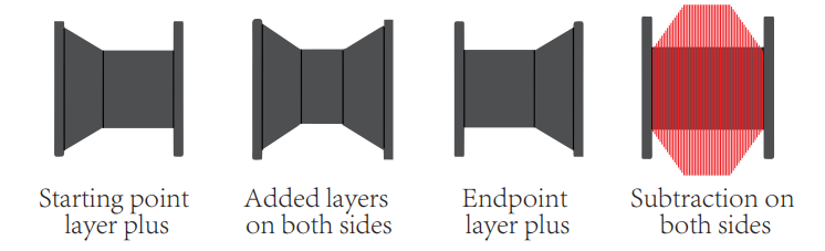
 The above picture shows the range of the spool that can be wound and the inner and outer widths of the spool
  Interface description of the monitoring screen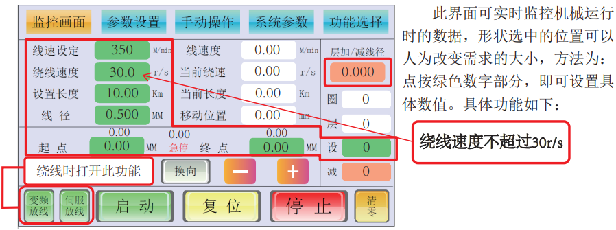
| Function button | Unit | Function Description |
| Wire Speed Setting | M/min | Preset the operating speed of the machine during winding; higher values mean faster speed. |
| Winding speed | r/s | Preset the winding speed; higher values mean faster speed (maximum speed: 30 r/s). |
| Set the length | Km/M | Set the required winding length; red font indicates meter-counting mode. |
| Wire Diameter | MM | Diameter of the wire. |
| Start Point (-/+) | MM | Winding start end; fine-tune by increasing/decreasing values if the position is inaccurate. |
| End Point (-/+) | MM | Winding end; fine-tune by increasing/decreasing values if the position is inaccurate. |
| Variable-Frequency Pay-off | Assists rapid pay-off for faster pay-off speed; enable during spool winding. | |
| Servo Pay-off | Accelerates wire passing speed at the encoder for faster winding; must be enabled during winding. | |
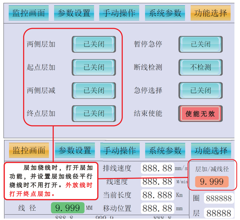
| Layer Addition/Reduction Wire Diameter | MM | Wire diameter setting for layer addition/reduction modes during winding. |
| Cycles | Real-time number of cycles in meter-counting mode. | |
| Layers | Real-time number of layers in meter-counting mode. | |
| Set | L | Decreasing wire diameter size to be adjusted when the preset number of layers is reached. |
| Decrease | MM |
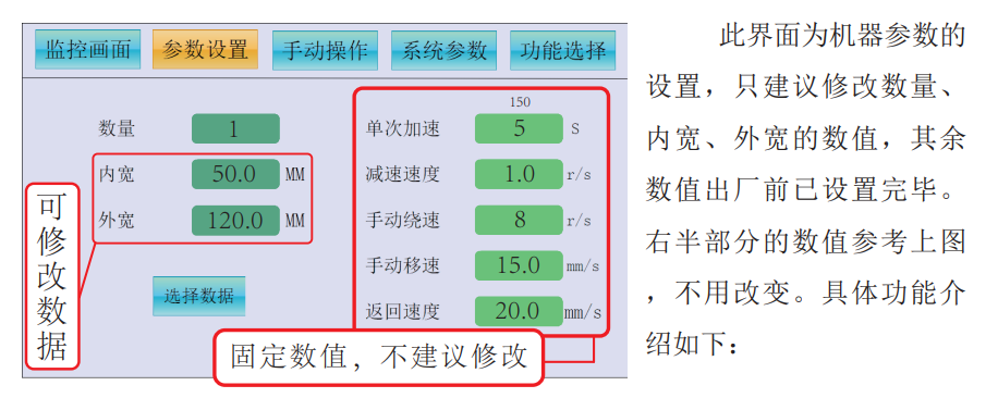
| Function button | Unit | Function Description |
| Quantity | Piece(s) | Number of spools to be wound. |
| Inner width | MM | Inner width of the target spool (winding width). |
| Outer width | MM | Outer width of the target spool (must be accurate to ensure precise switching to the next spool during multi-spool winding). |
| Single Acceleration | MS | Time for winding speed to reach normal from 0; higher values mean longer acceleration time. |
| Deceleration Speed | r/s | Speed when winding is about to end; higher values mean faster speed (recommended to be less than winding speed). |
| Manual Winding Speed | r/s | Winding speed in manual mode. |
| Manual Moving Speed | mm/s | Moving speed of the wire arrangement motor in manual mode. |
| Return Speed | mm/s | Reset speed of the wire arrangement motor after winding is completed. |
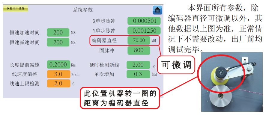
| Function button | Unit | Function Description |
| Constant speed acceleration time | MS | In parallel winding mode: Time to accelerate from standstill to constant speed. Larger values mean longer acceleration time. |
| Constant speed deceleration time | MS | In parallel winding mode: Time to decelerate from constant speed to stop. Larger values mean longer deceleration time. |
| Length Advance Deceleration | K M | Starts decelerating when the remaining winding length reaches this value. |
| X Single-Step Pulse | Winding pulse: System preset to 0.000501; no modification needed. | |
| Y Single-Step Pulse | Wire Arrangement pulse: System preset to 0.001250; no modification needed. | |
| Encoder Diameter | M M | Diameter of the length-counting wheel; determines the accuracy of length-counting parameters. |
| Pulses per Cycle | Number of pulses generated per winding cycle; system preset to 800; no modification needed. | |
| Wire Break Detection Delay | S | Time to detect wire breakage. Larger values mean slower response to wire breakage. |
| Single Increase | M M | Gap between the lead screw and slider; preset to 0.3; no modification needed. |
| Wire Speed Deviation | M / m i n | Speed deviation per minute during winding. |
| Wire Speed Upper Limit Detection | S | Time to detect when wire speed reaches the upper limit. |